Commander
The full board
Everything a twin-tank model submarine needs between its receiver and its machinery, on a board 80 mm by 52 mm, built on a Raspberry Pi Pico 2 W.
Designed and rule-checked. Firmware run on a simulated boat. Not yet built.
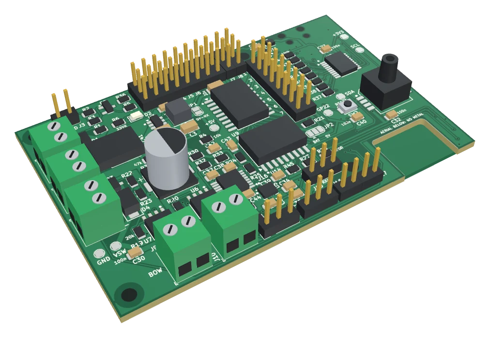
A 3D model made from the board's manufacturing files, with simple blocks for the parts. Not a photograph: no board has been built yet. The Pico is on the other face: press Pico face to turn the board over.
What it does
Nine jobs, one board
- Twin piston tanksDrives the bow and stern tank motors and reads each piston's position from its pot. A trim channel shifts water from one tank to the other, and the two pistons are kept in step.
- Pitch regulatorHolds the boat level, or at an angle you set, with the rear planes.
- Depth regulatorHolds a depth with the front planes. With the regulators on, the planes stick moves the depth to hold; with them off it moves the planes directly.
- Water detectorTwo probes, forward and aft, with a trip level you set. Water on either brings the boat up and flashes a code that tells you which end.
- Battery monitorA warning while the boat is still under control, then emergency surfacing at the cut-off voltage.
- FailsafeLost signal, low battery, water in the hull, too deep, or the depth reading lost below 20 cm: both tanks driven empty and the front planes to full rise.
- Emergency ascentA gas-cylinder valve, opened from a switch on the transmitter, or by the board itself when a failsafe has not brought the boat up.
- Lights and working featuresRunning lights, search light, two torpedo releases and a rotating aerial, each on the radio channel and switch position you choose. A torpedo fires only after its switch has been seen in the off position.
- Power and setupMagnet switch-on, setup from a phone over the board's own Wi-Fi, and switch-off from the phone.
It does not steer the boat or run the drive motor: the rudder servo and the speed controller plug into the receiver as usual, and the board's BOAT terminal switches their supply. It is for boats with piston tanks. A boat with one ballast pump wants the Mini, which comes later.
How it is built
A Pico on a carrier
The Raspberry Pi Pico 2 W is a small, widely sold controller board. It brings the processor, its memory, the Wi-Fi radio and aerial, a micro-USB socket and a button for loading firmware. The Commander is the board it is soldered to, which carries everything a submarine needs and the Pico lacks: the tank drivers, the sensors, the magnet switch, the switched outputs, the buffers for the radio and servo signals, and the connectors.
Using a Pico keeps the hardest parts of the circuit in a module that Raspberry Pi already makes in large numbers and has had approved as a radio, and has said it will go on making until at least 2040.
How it is made
By hand, one face
Every part except the Pico is on one face, and nothing is too small to place with tweezers. Each board will be pasted through a stencil, populated and soldered with hot air by hand, then tested on a rig with tank motors, servos and a receiver before it is posted.
The same choices make the board one you can mend: the parts have printed numbers beside them, and the circuit diagram and parts list come with it.
Connections
What plugs in where
Screw terminals for the battery, the boat's supply, the gas valve and the two tank motors. Pin headers for everything else: three-pin servo plugs for the receiver, servos and pots, two-pin plugs for the reed switch, the probes and the outputs.
Parts face
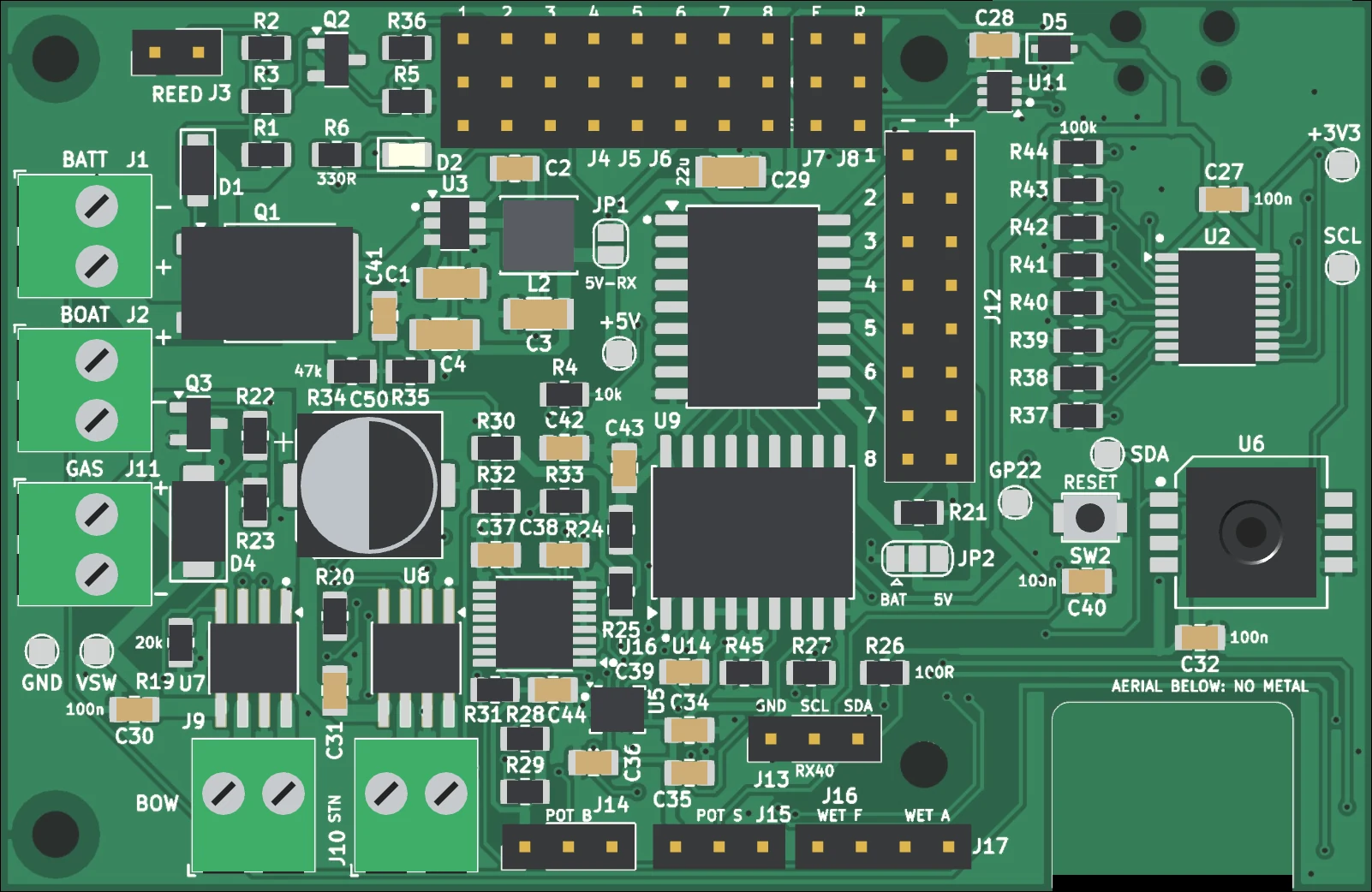 12345678910111213141516
- BATT Battery, 7 to 14 V.
- BOAT Switched battery out to the speed controller and the rest of the boat, about 6 A.
- GAS Solenoid valve for the emergency gas blow, 2 A.
- BOW Bow piston-tank motor.
- STN Stern piston-tank motor.
- REED Magnet switch. No polarity.
- CH 1 to 8 Patch leads from the receiver: eight columns of three pins.
- F and R Front and rear plane servos.
- Outputs 1 to 8 Lights, search light, two torpedoes, aerial, spare, alarm lamp, buzzer.
- POT B and POT S Position pot on each piston tank.
- WET F and WET A Water probes, forward and aft.
- RX40 For the RX40 receiver, when it comes. Left empty with any other receiver.
- Pressure sensor A tube from its port to the outside of the hull.
- RESET Restarts the controller.
- Lamp Lights when the board is on.
- Aerial cut-out The Pico's aerial lies over this gap. Keep metal, batteries and wiring away from this corner.
Pico face
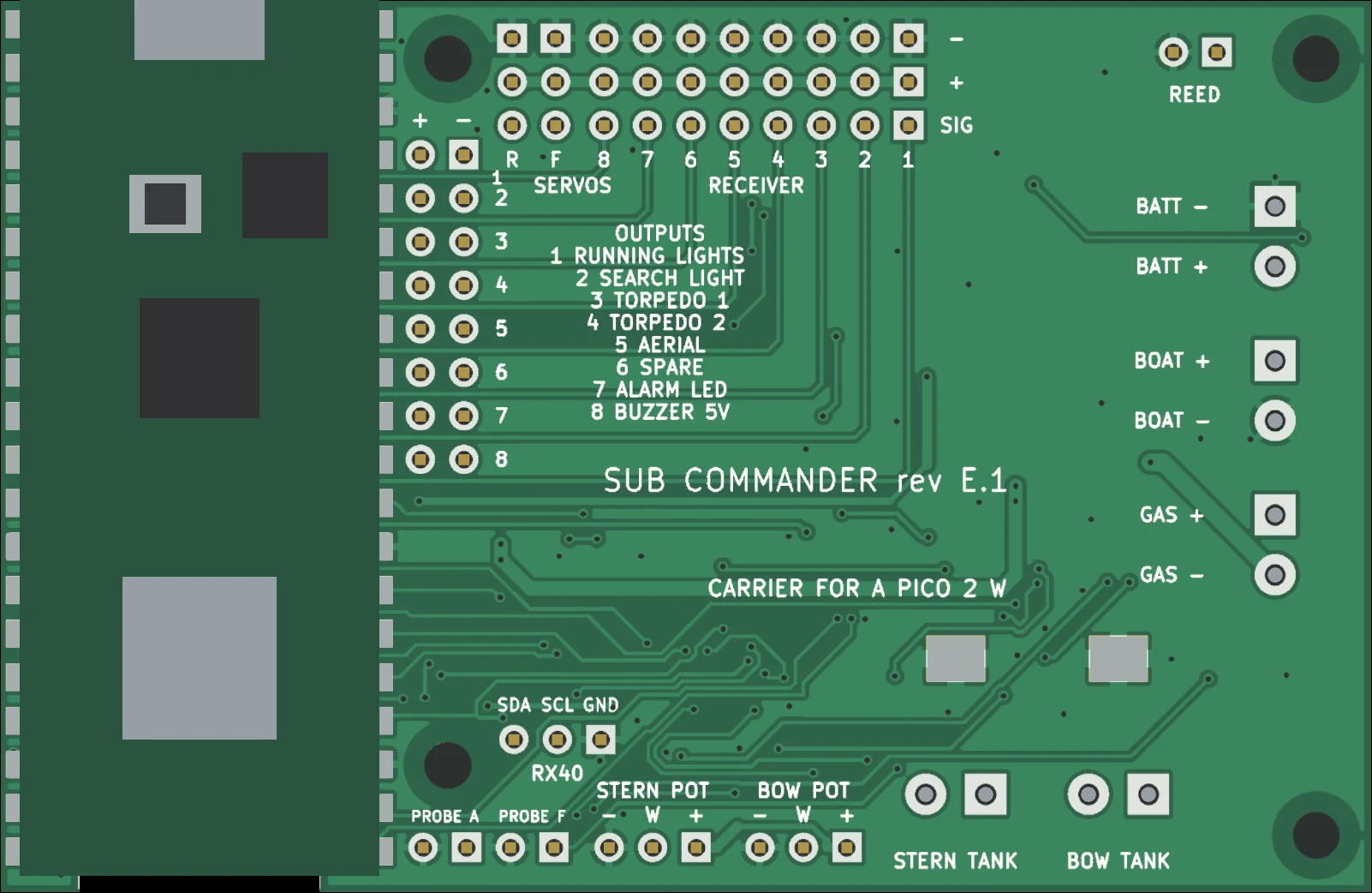 1234
1234- Micro-USB On the Pico, at the top edge of the board. For loading firmware.
- BOOTSEL The Pico's button. Held while plugging in USB for the first firmware load.
- Radio The Pico's Wi-Fi, for the setup page. Its aerial is at the bottom corner, over the cut-out.
- Legends Every connector is named on this face as well.
Drawn from the 3D model of the board, not a photograph.
The setup page
Six tabs
Status, Tanks, Sensors, Tuning, Extras and Power. Every setting has a labelled control, and most say what they do in plain words.
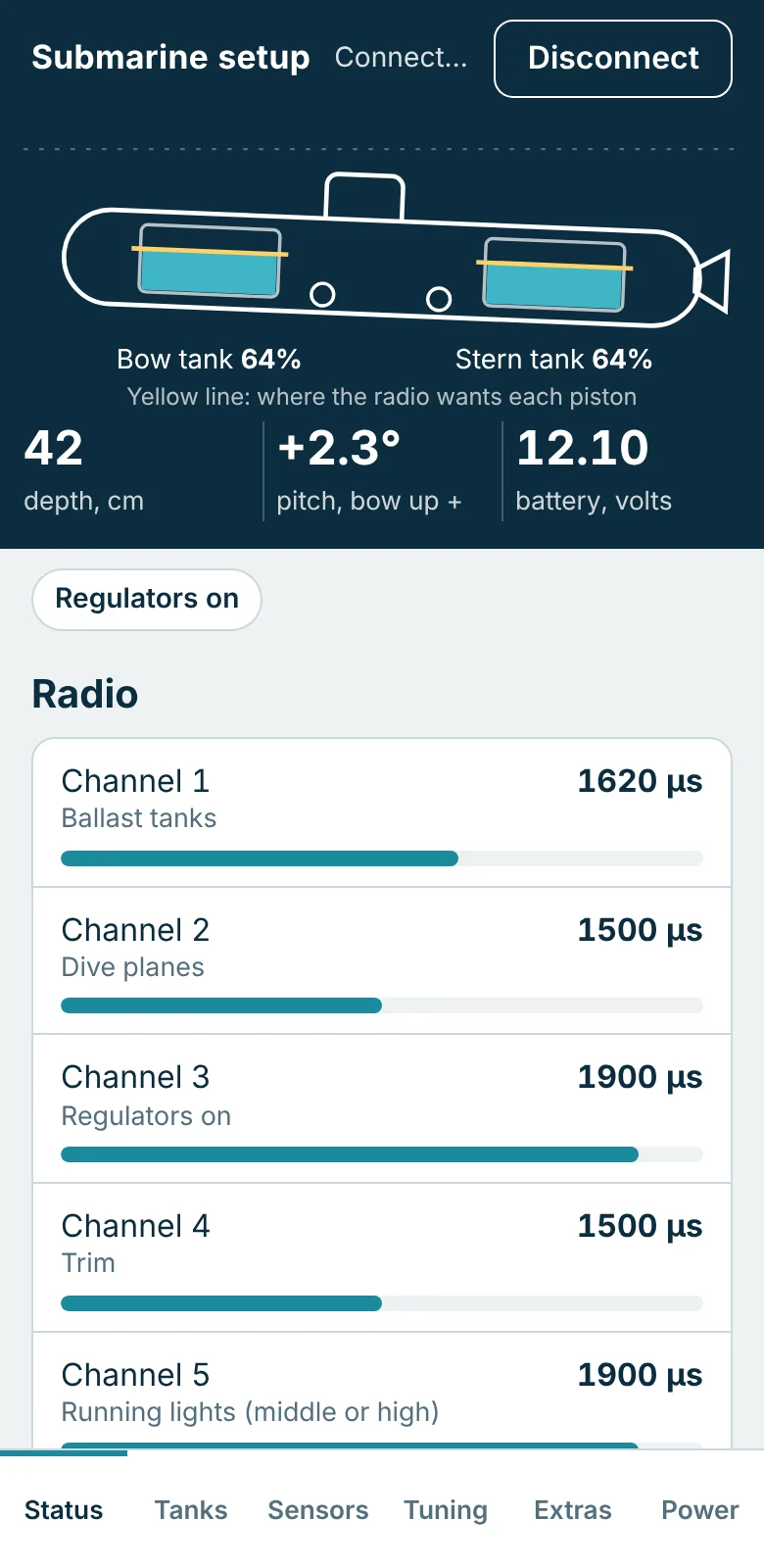
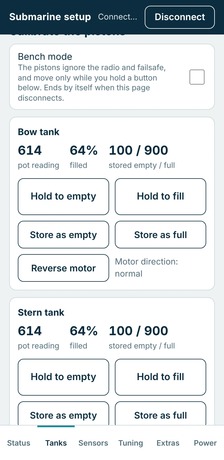
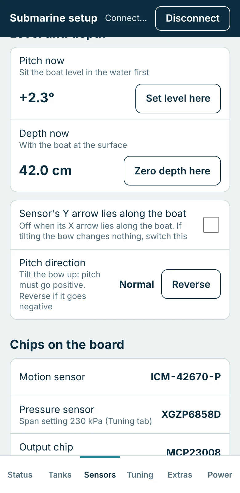
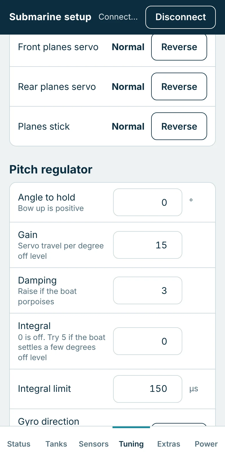
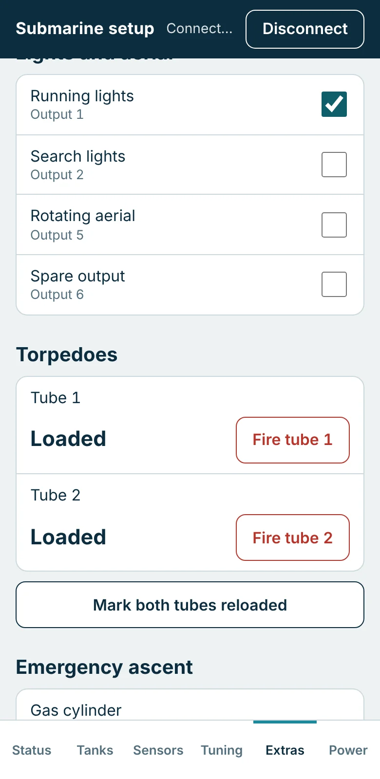
These are pictures of the real setup page, served by the board's own firmware running on a computer against a simulated boat. No hardware was involved.
Source available
Read it, change it, load your own
The firmware and the setup page will be published in full when the campaign opens.
A controller that decides when your boat surfaces should not be a sealed box. If you want the planes to behave differently, another failsafe, or a new use for an output, the code is there to change, and the original can always be put back.
The licence the source is published under will be stated with it.
- The firmware. One Arduino sketch, with plain-English comments throughout: what each setting does, and what each failsafe does and why.
- The setup page. One HTML file. Open it on a computer and it runs against a pretend boat, so you can try a change before it goes near the water.
- Free tools. It builds with the free Arduino program and the Arduino-Pico core. Nothing to buy and no account.
- No programmer. Your own version loads over the Pico's USB socket, and the original goes back the same way.
- The circuit too. The circuit diagram and the parts list come with the board, so it can be mended.
Specification
The numbers
| Size | 80 × 52 mm, 1.6 mm thick, two copper layers. A 14 × 11 mm cut-out at one corner, under the Pico's aerial. |
|---|---|
| Construction | About 75 surface-mount parts on one face, with no resistor or capacitor smaller than 2 × 1.25 mm, placed by hand with a stencil and hot air. A Raspberry Pi Pico 2 W soldered flat to the other face. |
| Mounting | Four M2.5 holes. The 26 mm of board under the Pico reaches past the last pair. |
| Battery | 7 to 14 V. No reverse-polarity protection: use a polarised connector. |
| Through the board to BOAT | About 6 A, switched by the magnet latch |
| Receiver inputs | 8 servo-pulse inputs, 3.3 V or 5 V, buffered. Any function can be put on any channel. |
| Servo outputs | 2: front planes and rear planes, buffered |
| Tank drivers | 2 reversible motor drivers, current limited to 3.2 A each, 20 kHz drive. Each tank has a position-pot input and a stall guard. |
| Switched outputs | 8, each sinking up to about 300 mA, or about 100 mA each with all eight on. Outputs 1 to 6 switch battery voltage, or 5 V by solder jumper (0.5 A in total); 7 is the alarm lamp, 8 the buzzer. |
| Gas valve output | 2 A, with a diode across the coil |
| Water probes | 2 inputs, forward and aft, with a trip level set on the phone |
| Battery monitor | Warning voltage and cut-off voltage, both adjustable |
| Depth | Digital absolute pressure sensor with a tube port (CFSensor XGZP6858D). It reads to about 10 m of water in its catalogue 20 to 200 kPa version, and to about 15 m in a 20 to 250 kPa version if the maker will supply it. |
| Pitch | Accelerometer and gyro on the board (TDK ICM-42670-P). Mount the board flat, any way round, and choose the axis on the phone. |
| Control loop | 50 times a second, on its own processor core, with a watchdog that restarts the controller if the loop ever stops for two seconds. Wi-Fi runs on the other core. |
| Controller | Raspberry Pi Pico 2 W: RP2350A, 4 MB program memory |
| Setup link | The Pico's own 2.4 GHz Wi-Fi as an access point, page at 192.168.4.1. The same commands work over USB. |
| Firmware | Source published in full: an Arduino sketch and the setup page. Loaded over the Pico's micro-USB socket with its BOOTSEL button; no programmer needed. A RESET button on the board. |
| RX40 link | Three-pin header (GND, SCL, SDA, 3.3 V signals) for the RX40 receiver, when it comes |
| Power switch | Magnet and reed switch to turn on. Off from the phone, or by itself after a set time with no radio and no phone. |
| Regulators | 5 V at 2 A (switching); the Pico makes the 3.3 V. A solder jumper lets the 5 V feed the receiver and servos. |
Design figures, taken from the circuit and the parts' data sheets. None has been measured on a finished board yet. Mounting holes and radio channels.
In the boat
What you add
- A radio set and receiver that work under water, with up to eight channels for the board.
- Two piston tanks, each with a motor and a position pot.
- Servos for the front and rear planes.
- A 7 to 14 V battery on a polarised connector.
- A reed switch and a magnet, a tube for the pressure sensor, and two water probes.
- If wanted: a gas cylinder and solenoid valve, lights, torpedo releases, a buzzer.
Know before you fit it
Limits
- It is not waterproof. The board lives in the dry part of the hull. Only the pressure tube goes outside.
- No reverse-polarity protection. A battery connected backwards will damage it.
- About 6 A through the board. A bigger drive motor takes its supply straight from the battery.
- Fix it firmly and flat. The pitch sensor is on the board, so the board must not move in the boat. The Pico stands about 4 mm proud of the other face: mount the board on spacers of 5 mm or more.
- Support the Pico end. The mounting holes stop short of it. Rest that end on a foam pad if the boat shakes.
- The tank motor drivers stop below about 6.5 V at the board. Set the battery cut-off above that.
- Keep metal away from the aerial corner, the corner with the cut-out.
- Pots, probes and the RX40 link run at 3.3 V. Do not put 5 V on those pins.
The Commander, first batch
Planned pledge £89, or £79 for the first 15 backers, plus postage. Join the list and you will hear the day the campaign opens.