RX40 receiver · coming later
No receiver crystals
A 40 MHz FM receiver for model submarines. A synthesiser takes the place of the receiver's plug-in crystal, and the channel is chosen on the controller's phone setup page.
Designed and rule-checked. Radio figures calculated. Not yet built.
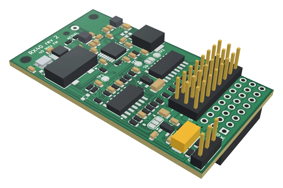
A 3D model made from the board's manufacturing files, with simple blocks for the parts. Not a photograph: no board has been built yet.
The RX40 is the least proven of the three boards. Its circuit and layout are finished and rule-checked, and its radio figures have been worked out from the parts' data sheets. None of that tells you how a receiver behaves in a hull, under water, beside a motor. Several part values can only be settled on the first board.
The Commander comes first. The RX40 is not part of the planned Kickstarter campaign, and it has no date and no price yet. Ask to be told when it is ready.
Why
Why 40 MHz, and why no receiver crystal
The 2.4 GHz radio that drives most models today is stopped by a few centimetres of water. Lower frequencies get through fresh water well enough to drive a submerged boat, which is why submarine modellers still use the 40 MHz band.
The trouble with 40 MHz sets is the crystals: one pair for each channel, easy to lose and harder to buy every year. The RX40 does away with the receiver's half of each pair. It makes its own tuning frequency with a synthesiser chip, set by the controller board. The transmitter keeps its crystal: to change channel you change that one, and pick the frequency printed on it from a list on the phone.
Specification
Design figures
| Band | 40.665 to 40.995 MHz |
|---|---|
| Channels | 34, in 10 kHz steps, chosen on the controller's phone setup page |
| Fine tune | Up to 3000 Hz either way |
| Transmitter | FM, PPM, up to 8 channels |
| Intermediate frequency | 455 kHz, ceramic filter and ceramic discriminator. 450 kHz parts fit the same pads, and the controller has a setting for them. |
| Outputs | 8 servo-pulse outputs, 3.3 V pulses |
| Supply | 4.5 to 6 V from the servo plugs' + row, about 30 mA |
| Aerial | Wire, about 1 m |
| Squelch | Calculated to open at about 1.7 microvolts at the aerial pad. Not measured. |
| Lost signal | Squelch stops the pulses, so the controller sees a lost signal and goes to failsafe |
| Size | 32 × 58.6 mm, two M2.5 holes. On the Commander it stands about 11 mm above it and reaches about 49 mm past its top edge. |
| Construction | 71 surface-mount parts on one face. No coils to wind and no trimmers. |
How it works
From aerial to servo pulses
- Input filterTwo tuned circuits with fixed parts pass a band about 3 MHz wide round 40.8 MHz and keep strong signals far from the band out of the mixer.
- MixerThe signal is mixed with a local oscillator 455 kHz below the transmitter's frequency.
- SynthesiserThe local oscillator: a clock-generator chip with one fixed crystal, set over two wires by the controller. This is what replaces the plug-in crystal.
- Channel filterA 455 kHz ceramic filter selects the one channel.
- Limiter and detectorThe narrow-band FM receiver chip limits the signal and, with a ceramic discriminator, recovers the transmitter's pulse train.
- Pulse slicerA comparator turns the small recovered waveform into clean logic pulses.
- SquelchWhen the chip's signal-strength output falls below a set level, the pulses are stopped, so the controller goes to failsafe.
- Channel decoderA counter deals the pulses out to eight outputs, one per channel, and resets in the gap between frames.
Connections
What goes where
A socket underneath for the Commander, a block of servo pins on top, and a three-pin header for the lead that carries the channel setting.
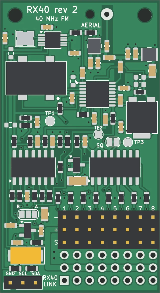 12345678
- Aerial About 1 m of thin wire, threaded through the plain hole beside the pad so that the hole takes the pull.
- Mounting holes Two M2.5 holes at the aerial end.
- Test pads Signal strength, the recovered pulse train and the sliced pulses, for setting up the first board.
- Squelch bridge Joined as made. Cut only for tests: the failsafe depends on it.
- Polarity bridge Changed once if the transmitter's pulses are the other way up.
- Channels 1 to 8 Servo pins on top: rudder, speed controller, and patch leads to a Mini.
- Socket underneath Pushes on to the Commander's receiver pins, channel 1 to channel 1.
- RX40 link Three-wire lead to the controller: GND, SCL, SDA.
Drawn from the 3D model of the board, not a photograph.
Fitting
On the Commander
The socket underneath pushes on to the Commander's eight receiver columns, and a three-wire lead of about 80 mm joins the two RX40 headers. The speed controller and rudder servo plug into the pins on top of the receiver. The receiver takes its 5 V from the + row: from the speed controller if it supplies one, otherwise bridge the Commander's 5V-RX jumper.
The receiver stands about 11 mm above the Commander and reaches about 49 mm past its top edge, so allow for that length in the boat. It covers the Commander's power lamp, which is then seen only from the side. In a boat that gets knocked about, fix the aerial end down on two pillars as well.
The RX40 was laid out against an earlier drawing of the Commander. The Commander has since been redrawn around a Pico, with its servo pins slightly closer to the receiver pins, so the fit has to be checked again before the RX40 is offered.
Fitting
With the Mini
The Mini has no receiver socket and does not power a receiver. Plug the speed controller, with its 5 V supply, and the rudder servo into the receiver. Run three servo patch leads from the receiver channels you choose to the Mini's pins 1, 2 and 3, and the three-wire lead between the two RX40 headers.
The patch leads also carry the 5 V to the Mini's pins for its two plane servos.
In use
Changing channel
Change the crystal in the transmitter. Pick the same frequency on the phone. That is all.
- Transmitter channel. A list of the 34 frequencies from 40.665 to 40.995 MHz. The receiver follows as soon as you choose.
- Fine tune. Up to 3000 Hz either way, set once for each board with a frequency counter. Left at 0 otherwise.
- Intermediate frequency. 455 or 450 kHz, to match the filter fitted on the receiver.
- No RX40 fitted. The setting as the controller comes. Nothing is then sent on the link, and any other receiver can be used.
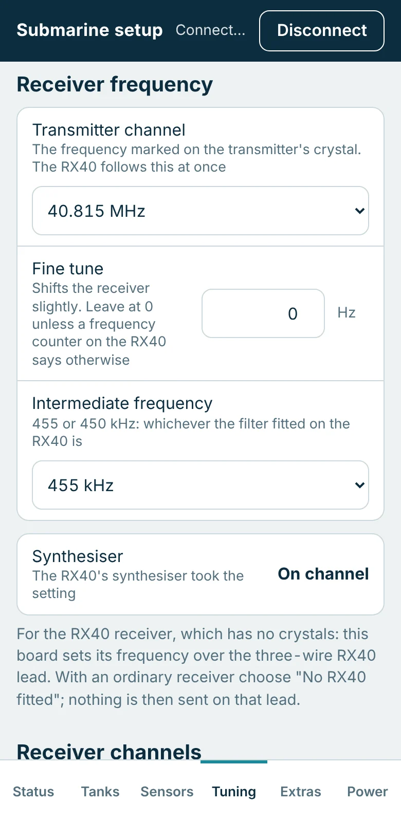
These are pictures of the real setup page, served by the board's own firmware running on a computer against a simulated boat. No hardware was involved.
What is not settled
Known weak points
Better to hear them now than after a boat is on the bottom.
- Nothing has been measured. The sensitivity and squelch figures are calculated from the chip's data sheet and a model of the input filter.
- No image rejection. The input filter is wide, to cover the band without adjustment, so a signal 910 kHz below the channel in use (39.755 to 40.085 MHz, just below the model band) is received as strongly as the wanted one. A strong transmitter there could disturb it.
- The detector is not proven. The ceramic discriminator on the board is not the type the receiver chip's data sheet was measured with. The board has pads for two other ways of doing the job if it will not do.
- Values to settle on the first board. A few small capacitors and resistors in the input filter, detector and squelch are starting values. The filter values, once found on a prototype, hold for every board of the same layout. The aerial coupling and the squelch level depend on the boat, and the fine tune is set for each board.
- 3.3 V output pulses. The Commander and Mini accept them, and so do most servos and speed controllers. A few old ones want 5 V pulses and will not move.
- Few sources for some parts. The receiver chip is stocked by one UK distributor, and the ceramic filter and discriminator by one Chinese one. Each has a named stand-in that fits the same pads.
- Radio approval. A receiver offered for sale needs its own compliance assessment. That has not started.
The Commander comes first
The RX40 follows once the Commander has been built and proved. Join the launch list and tick the RX40 to hear when it is ready.